FAQ on Farmall Cubs, Page 2
Written by Bob Brooks Updated by Jim Becker, October 2002
Frequently Asked Questions about Farmall Cubs.
1) Why does my Cub have 2 holes in the hood on the right side?
2) Where is my water Pump?
3) I have a wiring problem with my Cub. How are the electrical components supposed to be connected?
4) I was mowing with my Cub and the PTO quit working, what’s wrong with it?
1) Why does my Cub have 2 holes in the hood on the right side?
These holes are used to oil the Generator. After approximately every 60 hours of run time insert an oilcan spout through each hole. Lift the oil cap on the generator, and apply 2 to 3 drops of SAE-20 oil to each cup.
2) Where is my water Pump?
The Farmall Cub, like a lot of tractors designed during this period, uses a thermosyphon cooling system.
The engine does not have a water pump, but relies on the principle that warm water rises. The hot water flows out of the motor, to the top of the radiator, where it cools and drops through the radiator back into the bottom of the engine, where it repeats the process.
This system is self-regulating, and has worked on these tractors for almost 50 years. During cold weather operation, it may be necessary to block some of the airflow through the radiator, in very cold weather the cooling system may overcool the engine, and not allow it to reach operating temperatures. The system is capable of cooling the engine adequately during summer weather.
Note: If the radiator is filled to the top, it will overflow when warm. This is normal as the system will set it’s own water level. Early Cub’s used a non-pressurized cooling systems. In later years the system utilized a low pressure cap, about 2.5 -3 lbs. of pressure.
3) I have a wiring problem with my Cub. How are the electrical components supposed to be connected?
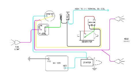
The correct wiring of your Cub depends on which verson of the Cub you have and what equipment is on the tractor. Major items that change the wiring are:
– 6 volt or 12 volt battery.
– Magneto or battery ignition.
– Generator cut-out or regulator.
– Lighting attachment or not.
The diagrams at the right cover most versions of Cub wiring. The first matches the earliest model Cubs. How much of this wiring was installed on any individual tractor depended on which attachments were installed. The second diagram matches the earliest models that had battery ignition and a voltage regulator. At serial number 210,001 (10,001 for Lo-Boys) a few changes were made, but the second diagram would still be substantially correct.

early wiring diagram – click to enlarge

later wiring diagram – click to enlarge
4) I was mowing with my Cub and the PTO quit working, what’s wrong with it?
There are several different reasons why this might happen. A common situation is that suddenly the PTO makes a grinding noise and throws itself out of gear. The engagement lever is already in the rear gate of the shifter guide plate, and the PTO refuses to re-engage.
The most common cause is probably an excessively worn shifter pin. But lets step through the possible problems in an orderly fashion, starting with the easiest to check and repair.
For the PTO to engage properly, and stay engaged under a load, the clutch (a sliding collar with an internal spline) that joins the two shafts in the transmission housing must be moved forward at least one half inch, or about one half the length of its internal spline. This action couples the main driveshaft (from the engine) with the PTO output shaft, turning it counterclockwise at engine speed.
The coupling collar is moved and held in place by the shifter pin, which is controlled by the PTO lever. Before doing any internal investigation, look at the lever and the guide plate. Make sure the lever is not bent and that the guide plate is in it’s normal position. The guide is held by one bolt and a small nub to help keep it in line. Straighten and adjust these parts as necessary. If this doesn’t cure the problem, or if the same problem recurs in a short time, you will have to look internally.
For the collar to engage properly, the two shafts that it couples together must be very close, end to end. If the forward transmission driveshaft bearing retainer is installed backwards, the main driveshaft can move forward, and pull away from the collar. This decreases the support provided by the pilot bushing in the end of the shaft, and leads to wear on the bushing and eventual shaft misalignment. Shaft misalignment increases the pressure on the collar under load, and forces it rearward, accelerating the wear on the front face of the shifter pin. Once the pin is worn down, it cant move the collar far enough forward to engage the shaft, and the PTO will throw itself out of gear.
Another cause is due to rearward movement of the PTO output shaft, setting up the same failure conditions. Early cubs used an output shaft with the rear support bearing staked in position. A later design does away with the stakes and substitutes a snap ring, which is less failure prone. If the small stakes on the shaft wear down, they will allow the shaft to push rearward through the bearing and disengage the PTO while totally wiping out the shifter pin.
Diagnose the problem by removing the rear PTO bearing retainer assembly. You may choose to remove the entire rear cover plate from the transmission housing. If so, you will need to drain the oil from the transmission before you start the disassembly. Draining and replacing the oil is a good practice during this type repair in any case. Remove the bolt on the transmission cover rear corner that holds the shift lever guide plate, and allow the shift lever to rotate forward while pulling the PTO shaft rearward out of the housing.
Remove the cotter pin from the end of the shift lever and pull the lever out of the end of the shifter arm. Remove the bushing on the end of the shifter arm. Reach into the rearend housing with your hand and pull the shifter arm out of the casting.
Inspect the shifter pin on the end of the arm for wear. If it has more than a small flat on the side its no longer serviceable.
Inspect the coupling collar on the shaft, and the bearing retention in the housing. If the bearing is staked onto the shaft, the stakes should be clearly visible, and the bearing should be seated fully in the housing. Try to move the shaft through the bearing if you suspect it has worn stakes. It should not move laterally at all. This can actually be checked prior to removal by trying to pull the shaft rearward. If theres any movement, the bearing isnt being properly retained for some reason. If you have a snap ring retainer, verify that it is holding the bearing in place on the shaft.
Inspect the coupling collar for excessive wear. There should be a 1/16 chamfer on the end of the spline where it engages with the main shaft. The splines themselves should be fairly square and sharp.
Look inside with a flashlight and inspect the end of the main driveshaft. The splined end should be uniformly rounded, which eases engagement with the coupling. All shafts were made this way, and shouldnt be mistaken for excessive wear. Inspect the pilot bushing in the end of the shaft. Its a very thin bronze bushing. Is it still round, or is it worn and egg shaped? These bushings are still available from Case/IH for about $3, and should be replaced if worn.
At this point, remove the coupling collar from the output shaft by backing out the set screw and sliding it off the end of the shaft. Remove the oil filler plug on the top of the rearend housing. Put the shaft back into the rearend and look through the oil filler hole with a flashlight. The end of the shaft should go all the way into the pilot bushing and not be excessively sloppy. The ends of the two shafts should meet within 1/8. If the shafts meet, its okay. If they dont you need to determine the cause. Is you output shaft too far rearward, or has the main driveshaft moved forward?
After replacing worn parts and making sure the two shafts are in proper alignment and close together on the ends, re-assemble the PTO. Put the collar back on the PTO output shaft. Be sure to install it the same side in as it was installed before. The set screw should be turned in far enough to keep the collar from sliding completely off the shaft, but not so far that it interferes with normal sliding on the shaft. Install the shifter arm and replace the lever on the outside of the housing. Do not install the guide plate yet. Placing the PTO shaft back in the housing and engaging the collar with the shifter pin is a little tricky, but not impossible. It helps to shine a flashlight through the oil filler hole, and manipulate the shift lever into the groove in the collar visually while lining up the pilot with the bushing. Some cub mechanics advocate leaving the set screw out of the coupling collar, and placing the collar on the end of the driveshaft by hand while engaging it with the shifter pin. Then the collar can be held in position with the shift lever while installing the output shaft. If you choose this option, beware the next time you remove the shaft. It must be held forward with the shift lever or it will drop into the rear end in front of the ring gear, and might be hard to retrieve.
Once the output shaft is installed, install the shift lever guide plate and bolt it down. Look through the oil filler hole again and make sure the coupling collar is moving all the way forward and into engagement with the driveshaft. It should move to within 1/8 of the wall of the transmission. Move the shift lever through the normal range and be sure the collar engages and disengages properly.
If everything looks good at this point, replace or top off the gear oil in the transmission housing and try it out. Additional information on transmission lubrication is in your Owner’s Manual.
Do you have other questions about the farmall Cub? An active discussion group dedicated to the Cub can be found on another page of this site.
ATIS Farmall Cub Internet Discussion Board
Photographs used to illustrate this FAQ have been provided by a number of Cub and Lo-Boy owners from throughout the country. The photographer of each picture, and often some additional detail about each tractor, can be seen by mousing over the picture. Higher resolution copies of most of these pictures, as well as many other Cub and Lo-Boy photographs can be found at these sites.
Farmall Cub – Home Page
IHC cub loboy series
Data sources are the IH Tractor Identification Guide by Kenneth Updike, the Farmall Cub Parts Book published by International Harvestor and the HotLine Farm Equipment Guide.
